 网硕互联帮助中心
企业园区网络设计与实现
A.项目描述与需求
某公司 聘请你为其位于克拉科夫的新总部搭建一个 LAN。以下是在新楼宇中部署该网络的需求。
1.使用 Cisco Packet Tracer 实现该解决方案。
2.公司分配的网络地址为 192.168.1.0/20。
3.这栋 4 层楼的每一层都有不同部门办公。每个部门将划分到不同的 VLAN 和不同的子网。
4.三楼将部署一个无线接入点,最多可接入 1000 台设备。各楼层和部门的详细信息如下。
第 1 层:
行政与人力资源部:需要 90 台设备
销售与市场部:需要 200 台设备
第 2 层:
财务部:需要 80 台设备
公共关系部:需要 100 台设备
第 3 层:
IT 与通信部:需要 200 台设备
无线接入点:最多应连接 1000 台设备
第 4 层:
服务器机房:需要 20 台设备
5.应部署一台连接到 ISP 的核心路由器,并将两台三层交换机连接到该核心路由器。
核心路由器与 ISP 之间的网络地址:193.168.16.0/30
三层交换机 S1 与核心路由器之间的网络地址:192.168.19.164/30
三层交换机 S2 与核心路由器之间的网络地址:192.168.19.168/30
6.所有部门的设备都需要通过对应三层交换机上配置的 VLAN 间路由实现相互通信。
7.三层交换机应同时承担路由转发和二层交换功能。
8.网络中的所有终端设备应从位于服务器机房的 DHCP 服务器动态获取 IP 地址。
9.服务器机房中的设备应采用静态方式分配 IP 地址。
10.使用 OSPF 作为路由协议,在路由器与三层交换机之间通告路由。
11.在核心路由器上配置 NAT。
B.子网划分
基础网络:192.168.16.0/20
11000000.10101000.00010000.00000000 / 11111111.11111111.1111 0000.00000000
行政与人力资源部
网络地址:192.168.16.0/25
广播地址:192.168.16.127
所需设备数:90
为主机分配的可用 IP 地址数:126
财务部
网络地址:192.168.16.128/25
广播地址:192.168.16.255
所需设备数:90
为主机分配的可用 IP 地址数:126
销售与市场部
网络地址:192.168.17.0/24
广播地址:192.168.17.255
所需设备数:200
为主机分配的可用 IP 地址数:254
IT 与通信部
网络地址:192.168.18.0/24
广播地址:192.168.18.255
所需设备数:200
为主机分配的可用 IP 地址数:254
公共关系部
网络地址:192.168.19.0/25
广播地址:192.168.19.127
所需设备数:90
为主机分配的可用 IP 地址数:126
服务器机房
网络地址:192.168.19.128/27
广播地址:192.168.19.159
所需设备数:20
为主机分配的可用 IP 地址数:30
无线网络信息
网络地址:192.168.20.0/22
广播地址:192.168.23.255
所需设备数:1000
为主机分配的可用 IP 地址数:1022
C.网络拓扑
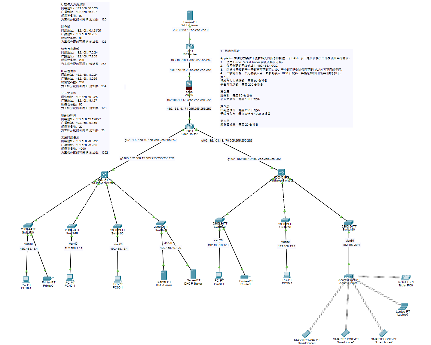
路由器和三层交换机均使用 OSPF 作为路由协议。
核心路由器上已配置 NAT。
三层交换机已配置 VLAN 间路由。
三层交换机与 2960 型号交换机之间的端口已配置为 trunk 端口。
2960 型号交换机与终端设备之间的端口已配置为 access 端口。
无线接入点采用 WPA2–PSK 认证并设置了密码。由于公共关系部的智能手机未输入正确密码,因此未连接到无线网络。
拓扑结构概览
#mermaid-svg-FQxUmiM6wIFacnUb{font-family:\”trebuchet ms\”,verdana,arial,sans-serif;font-size:16px;fill:#333;}@keyframes edge-animation-frame{from{stroke-dashoffset:0;}}@keyframes dash{to{stroke-dashoffset:0;}}#mermaid-svg-FQxUmiM6wIFacnUb .edge-animation-slow{stroke-dasharray:9,5!important;stroke-dashoffset:900;animation:dash 50s linear infinite;stroke-linecap:round;}#mermaid-svg-FQxUmiM6wIFacnUb .edge-animation-fast{stroke-dasharray:9,5!important;stroke-dashoffset:900;animation:dash 20s linear infinite;stroke-linecap:round;}#mermaid-svg-FQxUmiM6wIFacnUb .error-icon{fill:#552222;}#mermaid-svg-FQxUmiM6wIFacnUb .error-text{fill:#552222;stroke:#552222;}#mermaid-svg-FQxUmiM6wIFacnUb .edge-thickness-normal{stroke-width:1px;}#mermaid-svg-FQxUmiM6wIFacnUb .edge-thickness-thick{stroke-width:3.5px;}#mermaid-svg-FQxUmiM6wIFacnUb .edge-pattern-solid{stroke-dasharray:0;}#mermaid-svg-FQxUmiM6wIFacnUb .edge-thickness-invisible{stroke-width:0;fill:none;}#mermaid-svg-FQxUmiM6wIFacnUb .edge-pattern-dashed{stroke-dasharray:3;}#mermaid-svg-FQxUmiM6wIFacnUb .edge-pattern-dotted{stroke-dasharray:2;}#mermaid-svg-FQxUmiM6wIFacnUb .marker{fill:#333333;stroke:#333333;}#mermaid-svg-FQxUmiM6wIFacnUb .marker.cross{stroke:#333333;}#mermaid-svg-FQxUmiM6wIFacnUb svg{font-family:\”trebuchet ms\”,verdana,arial,sans-serif;font-size:16px;}#mermaid-svg-FQxUmiM6wIFacnUb p{margin:0;}#mermaid-svg-FQxUmiM6wIFacnUb .label{font-family:\”trebuchet ms\”,verdana,arial,sans-serif;color:#333;}#mermaid-svg-FQxUmiM6wIFacnUb .cluster-label text{fill:#333;}#mermaid-svg-FQxUmiM6wIFacnUb .cluster-label span{color:#333;}#mermaid-svg-FQxUmiM6wIFacnUb .cluster-label span p{background-color:transparent;}#mermaid-svg-FQxUmiM6wIFacnUb .label text,#mermaid-svg-FQxUmiM6wIFacnUb span{fill:#333;color:#333;}#mermaid-svg-FQxUmiM6wIFacnUb .node rect,#mermaid-svg-FQxUmiM6wIFacnUb .node circle,#mermaid-svg-FQxUmiM6wIFacnUb .node ellipse,#mermaid-svg-FQxUmiM6wIFacnUb .node polygon,#mermaid-svg-FQxUmiM6wIFacnUb .node path{fill:#ECECFF;stroke:#9370DB;stroke-width:1px;}#mermaid-svg-FQxUmiM6wIFacnUb .rough-node .label text,#mermaid-svg-FQxUmiM6wIFacnUb .node .label text,#mermaid-svg-FQxUmiM6wIFacnUb .image-shape .label,#mermaid-svg-FQxUmiM6wIFacnUb .icon-shape .label{text-anchor:middle;}#mermaid-svg-FQxUmiM6wIFacnUb .node .katex path{fill:#000;stroke:#000;stroke-width:1px;}#mermaid-svg-FQxUmiM6wIFacnUb .rough-node .label,#mermaid-svg-FQxUmiM6wIFacnUb .node .label,#mermaid-svg-FQxUmiM6wIFacnUb .image-shape .label,#mermaid-svg-FQxUmiM6wIFacnUb .icon-shape .label{text-align:center;}#mermaid-svg-FQxUmiM6wIFacnUb .node.clickable{cursor:pointer;}#mermaid-svg-FQxUmiM6wIFacnUb .root .anchor path{fill:#333333!important;stroke-width:0;stroke:#333333;}#mermaid-svg-FQxUmiM6wIFacnUb .arrowheadPath{fill:#333333;}#mermaid-svg-FQxUmiM6wIFacnUb .edgePath .path{stroke:#333333;stroke-width:2.0px;}#mermaid-svg-FQxUmiM6wIFacnUb .flowchart-link{stroke:#333333;fill:none;}#mermaid-svg-FQxUmiM6wIFacnUb .edgeLabel{background-color:rgba(232,232,232, 0.8);text-align:center;}#mermaid-svg-FQxUmiM6wIFacnUb .edgeLabel p{background-color:rgba(232,232,232, 0.8);}#mermaid-svg-FQxUmiM6wIFacnUb .edgeLabel rect{opacity:0.5;background-color:rgba(232,232,232, 0.8);fill:rgba(232,232,232, 0.8);}#mermaid-svg-FQxUmiM6wIFacnUb .labelBkg{background-color:rgba(232, 232, 232, 0.5);}#mermaid-svg-FQxUmiM6wIFacnUb .cluster rect{fill:#ffffde;stroke:#aaaa33;stroke-width:1px;}#mermaid-svg-FQxUmiM6wIFacnUb .cluster text{fill:#333;}#mermaid-svg-FQxUmiM6wIFacnUb .cluster span{color:#333;}#mermaid-svg-FQxUmiM6wIFacnUb div.mermaidTooltip{position:absolute;text-align:center;max-width:200px;padding:2px;font-family:\”trebuchet ms\”,verdana,arial,sans-serif;font-size:12px;background:hsl(80, 100%, 96.2745098039%);border:1px solid #aaaa33;border-radius:2px;pointer-events:none;z-index:100;}#mermaid-svg-FQxUmiM6wIFacnUb .flowchartTitleText{text-anchor:middle;font-size:18px;fill:#333;}#mermaid-svg-FQxUmiM6wIFacnUb rect.text{fill:none;stroke-width:0;}#mermaid-svg-FQxUmiM6wIFacnUb .icon-shape,#mermaid-svg-FQxUmiM6wIFacnUb .image-shape{background-color:rgba(232,232,232, 0.8);text-align:center;}#mermaid-svg-FQxUmiM6wIFacnUb .icon-shape p,#mermaid-svg-FQxUmiM6wIFacnUb .image-shape p{background-color:rgba(232,232,232, 0.8);padding:2px;}#mermaid-svg-FQxUmiM6wIFacnUb .icon-shape .label rect,#mermaid-svg-FQxUmiM6wIFacnUb .image-shape .label rect{opacity:0.5;background-color:rgba(232,232,232, 0.8);fill:rgba(232,232,232, 0.8);}#mermaid-svg-FQxUmiM6wIFacnUb .label-icon{display:inline-block;height:1em;overflow:visible;vertical-align:-0.125em;}#mermaid-svg-FQxUmiM6wIFacnUb .node .label-icon path{fill:currentColor;stroke:revert;stroke-width:revert;}#mermaid-svg-FQxUmiM6wIFacnUb :root{–mermaid-font-family:\”trebuchet ms\”,verdana,arial,sans-serif;}
Web Server外网服务区
ISP Router2911
ASA-FirewallASA 5505
CORE-Router2911OSPF + NAT
MLS13650-24PSVLAN10/40/60/70
MLS23650-24PSVLAN20/50/80
SW10 / Switch10VLAN10
SW40 / Switch40VLAN40
SW60 / Switch60VLAN60
SW70 / Switch70VLAN70
SW20 / Switch20VLAN20
SW50 / Switch50VLAN50
SW80 / Switch80VLAN80
PC10-1
PC40-1
PC60-1
DNS Server
DHCP Server
PC20-1
PC50-1
Access Point0
MLS1设计:
| Core – MLS1 | Core G0/1 192.168.19.166/30 | MLS1 G1/0/5 192.168.19.165/30 | 192.168.19.164/30 |
连线
连线
| Switch10 | FastEthernet0/1 | PC10-1 | FastEthernet0 | eStraightThrough |
| Switch40 | FastEthernet0/1 | PC40-1 | FastEthernet0 | eStraightThrough |
| Switch60 | FastEthernet0/1 | PC60-1 | FastEthernet0 | eStraightThrough |
| Switch70 | FastEthernet0/1 | DNS Server | FastEthernet0 | eStraightThrough |
| Switch70 | FastEthernet0/2 | DHCP Server | FastEthernet0 | eStraightThrough |
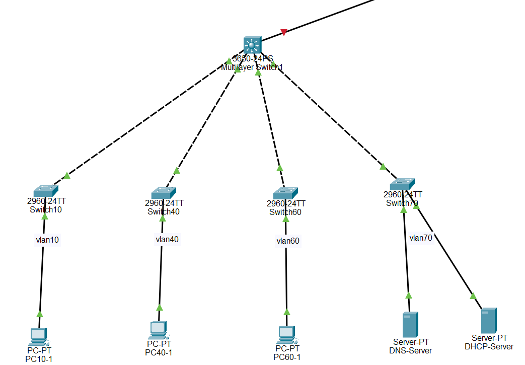
| Switch10 | GigabitEthernet0/1 | MLS1 | GigabitEthernet1/0/1 | eCrossOver |
| Switch40 | GigabitEthernet0/1 | MLS1 | GigabitEthernet1/0/2 | eCrossOver |
| Switch60 | GigabitEthernet0/1 | MLS1 | GigabitEthernet1/0/3 | eCrossOver |
| Switch70 | GigabitEthernet0/1 | MLS1 | GigabitEthernet1/0/4 | eCrossOver |
| Core Router | GigabitEthernet0/1 | MLS1 | GigabitEthernet1/0/5 | eStraightThrough |
MLS1中VLAN 与地址规划
| 10 | Administration-HR | 192.168.16.0/25 | 192.168.16.1 | MLS1 Vlan10 |
| 40 | Sales-Marketing | 192.168.17.0/24 | 192.168.17.1 | MLS1 Vlan40 |
| 60 | IT-Communication | 192.168.18.0/24 | 192.168.18.1 | MLS1 Vlan60 |
| 70 | Server-Room | 192.168.19.128/27 | 192.168.19.129 | MLS1 Vlan70 |
MLS1拓扑图
MLS1中二层交换机代码
例如 SW10 是行政与人力资源部交换机,PC 接口属于 VLAN 10:
enable
configure terminal
vlan 10
name ADMIN_HR
! PC 所接的端口
interface fastEthernet 0/1
switchport mode access
switchport access vlan 10
spanning–tree portfast
! 上联到 MLS1 的端口
interface gigabitEthernet 0/1
switchport mode trunk
switchport trunk allowed vlan 10
end
write memory
例如 SW40 是销售与市场,PC 接口属于 VLAN 40:
enable
configure terminal
vlan 40
name SALES_MARKETING
! PC 所接的端口
interface fastEthernet 0/1
switchport mode access
switchport access vlan 40
spanning–tree portfast
! 上联到 MLS1 的端口
interface gigabitEthernet 0/1
switchport mode trunk
switchport trunk allowed vlan 40
end
write memory
例如 SW60 是IT 与通信部,PC 接口属于 VLAN 60:
enable
configure terminal
vlan 60
name IT_COMMUNICATIONS
! PC 所接的端口
interface fastEthernet 0/1
switchport mode access
switchport access vlan 60
spanning–tree portfast
! 上联到 MLS1 的端口
interface gigabitEthernet 0/1
switchport mode trunk
switchport trunk allowed vlan 60
end
write memory
例如 SW70 是服务器机房,PC 接口属于 VLAN70:
enable
configure terminal
vlan 70
name SERVER_ROOM
! PC 所接的端口
interface fastEthernet 0/1
switchport mode access
switchport access vlan 70
spanning–tree portfast
! 上联到 MLS1 的端口
interface gigabitEthernet 0/1
switchport mode trunk
switchport trunk allowed vlan 70
end
write memory
MLS1(三层交换机 1)配置
MLS1(三层交换机) 的正确核心配置:它负责创建 VLAN 10、40、60、70,并作为这些 VLAN 的默认网关。
enable
configure terminal
! 开启三层交换和 VLAN 间路由
ip routing
! 创建 VLAN
vlan 10
name ADMIN_HR
vlan 40
name SALES_MARKETING
vlan 60
name IT_COMMUNICATIONS
vlan 70
name SERVER_ROOM
! VLAN 10:行政与人力资源部
interface vlan 10
ip address 192.168.16.1 255.255.255.128
no shutdown
! VLAN 40:销售与市场部
interface vlan 40
ip address 192.168.17.1 255.255.255.0
no shutdown
! VLAN 60:IT 与通信部
interface vlan 60
ip address 192.168.18.1 255.255.255.0
no shutdown
! VLAN 70:服务器机房
interface vlan 70
ip address 192.168.19.129 255.255.255.224
no shutdown
end
write memory
MLS1(三层交换机)上,把连接各二层交换机的物理接口设置为 Trunk。
enable
configure terminal
! 连接 SW10:只传递 VLAN 10
interface gigabitEthernet 1/0/1
switchport mode trunk
switchport trunk allowed vlan 10
exit
! 连接 SW40:只传递 VLAN 40
interface gigabitEthernet 1/0/2
switchport mode trunk
switchport trunk allowed vlan 40
exit
! 连接 SW60:只传递 VLAN 60
interface gigabitEthernet 1/0/3
switchport mode trunk
switchport trunk allowed vlan 60
exit
! 连接 SW70:只传递 VLAN 70
interface gigabitEthernet 1/0/4
switchport mode trunk
switchport trunk allowed vlan 70
exit
end
write memory
MLS1(三层交换机)上,把连接CoreRouter的物理接口设置ip地址
enable
configure terminal
! 连接 Core Router G0/1 的三层路由端口
interface gigabitEthernet 1/0/5
description TO_CORE_ROUTER_G0/1
no switchport
ip address 192.168.19.165 255.255.255.252
no shutdown
end
write memory
MLS1(三层交换机)上,建立OSPF 。
enable
configure terminal
router ospf 1
router–id 2.2.2.2
! Core ↔ MLS1 三层互联链路
network 192.168.19.164 0.0.0.3 area 0
! VLAN 10:行政与人力资源
network 192.168.16.0 0.0.0.127 area 0
! VLAN 40:销售与市场
network 192.168.17.0 0.0.0.255 area 0
! VLAN 60:IT 与通信
network 192.168.18.0 0.0.0.255 area 0
! VLAN 70:服务器机房
network 192.168.19.128 0.0.0.31 area 0
end
write memory
在MLS1确认配置生效:
下面确认二层交换机的配置:
1.show vlan brief:简要显示 VLAN 信息
VLAN Name Status Ports
—— ———————————————— ————– ———————————————–
1 default active Fa0/2, Fa0/3, Fa0/4, Fa0/5
Fa0/6, Fa0/7, Fa0/8, Fa0/9
Fa0/10, Fa0/11, Fa0/12, Fa0/13
Fa0/14, Fa0/15, Fa0/16, Fa0/17
Fa0/18, Fa0/19, Fa0/20, Fa0/21
Fa0/22, Fa0/23, Fa0/24, Gig0/2
10 ADMIN_HR active Fa0/1
2.show interfaces trunk:查看本交换机上哪些端口正在作为 Trunk 端口运行,以及每个 Trunk 端口允许传递哪些 VLAN。
Port Mode Encapsulation Status Native vlan
Gig0/1 on 802.1q trunking 1
Port Vlans allowed on trunk
Gig0/1 10
Port Vlans allowed and active in management domain
Gig0/1 10
Port Vlans in spanning tree forwarding state and not pruned
Gig0/1 10
3.show interfaces status:简要查看交换机所有物理端口当前的连接状态。
4.show interfaces trunk:查看本交换机上哪些端口正在作为 Trunk 端口运行,以及每个 Trunk 端口允许传递哪些 VLAN。
下面确认三层交换机的配置:
1.show running–config:ip routing、VLAN、SVI、OSPF 是否写入
2.show vlan brief
VLAN Name Status Ports
—— ———————————————— ————– ———————————————–
1 default active Gig1/0/6, Gig1/0/7, Gig1/0/8, Gig1/0/9
Gig1/0/10, Gig1/0/11, Gig1/0/12, Gig1/0/13
Gig1/0/14, Gig1/0/15, Gig1/0/16, Gig1/0/17
Gig1/0/18, Gig1/0/19, Gig1/0/20, Gig1/0/21
Gig1/0/22, Gig1/0/23, Gig1/0/24, Gig1/1/1
Gig1/1/2, Gig1/1/3, Gig1/1/4
10 ADMIN_HR active
40 SALES_MARKETING active
60 IT_COMMUNICATIONS active
70 SERVER_ROOM active
3.show interfaces trunk:上联 SW10/SW40/SW60/SW70 是否成为 Trunk
Port Mode Encapsulation Status Native vlan
Gig1/0/1 on 802.1q trunking 1
Gig1/0/2 on 802.1q trunking 1
Gig1/0/3 on 802.1q trunking 1
Gig1/0/4 on 802.1q trunking 1
Port Vlans allowed on trunk
Gig1/0/1 10
Gig1/0/2 40
Gig1/0/3 60
Gig1/0/4 70
Port Vlans allowed and active in management domain
Gig1/0/1 10
Gig1/0/2 40
Gig1/0/3 60
Gig1/0/4 70
Port Vlans in spanning tree forwarding state and not pruned
Gig1/0/1 10
Gig1/0/2 40
Gig1/0/3 60
Gig1/0/4 70
4.show ip interface brief:四个 VLAN 网关是否启用,Core 链路是否启用
Interface IP–Address OK? Method Status Protocol
GigabitEthernet1/0/1 unassigned YES unset up up
GigabitEthernet1/0/2 unassigned YES unset up up
GigabitEthernet1/0/3 unassigned YES unset up up
GigabitEthernet1/0/4 unassigned YES unset up up
GigabitEthernet1/0/5 192.168.19.165 YES manual up up
Vlan1 unassigned YES unset administratively down down
Vlan10 192.168.16.1 YES manual up up
Vlan40 192.168.17.1 YES manual up up
Vlan60 192.168.18.1 YES manual up up
Vlan70 192.168.19.129 YES manual up up
5.show interfaces gigabitEthernet 1/0/5 switchport:Gi1/0/5 是否已变成三层路由口
Name: Gig1/0/5
Switchport: Disabled
6.show ip route:本地路由是否存在
Codes: C – connected, S – static, I – IGRP, R – RIP, M – mobile, B – BGP
D – EIGRP, EX – EIGRP external, O – OSPF, IA – OSPF inter area
N1 – OSPF NSSA external type 1, N2 – OSPF NSSA external type 2
E1 – OSPF external type 1, E2 – OSPF external type 2, E – EGP
i – IS–IS, L1 – IS–IS level–1, L2 – IS–IS level–2, ia – IS–IS inter area
* – candidate default, U – per–user static route, o – ODR
P – periodic downloaded static route
Gateway of last resort is 192.168.19.166 to network 0.0.0.0
192.168.16.0/24 is variably subnetted, 3 subnets, 2 masks
C 192.168.16.0/25 is directly connected, Vlan10
L 192.168.16.1/32 is directly connected, Vlan10
O 192.168.16.128/25 [110/3] via 192.168.19.166, 01:04:09, GigabitEthernet1/0/5
192.168.17.0/24 is variably subnetted, 2 subnets, 2 masks
C 192.168.17.0/24 is directly connected, Vlan40
L 192.168.17.1/32 is directly connected, Vlan40
192.168.18.0/24 is variably subnetted, 2 subnets, 2 masks
C 192.168.18.0/24 is directly connected, Vlan60
L 192.168.18.1/32 is directly connected, Vlan60
192.168.19.0/24 is variably subnetted, 6 subnets, 4 masks
O 192.168.19.0/25 [110/3] via 192.168.19.166, 01:04:09, GigabitEthernet1/0/5
C 192.168.19.128/27 is directly connected, Vlan70
L 192.168.19.129/32 is directly connected, Vlan70
C 192.168.19.164/30 is directly connected, GigabitEthernet1/0/5
L 192.168.19.165/32 is directly connected, GigabitEthernet1/0/5
O 192.168.19.168/30 [110/2] via 192.168.19.166, 01:04:09, GigabitEthernet1/0/5
O 192.168.20.0/22 [110/3] via 192.168.19.166, 01:04:09, GigabitEthernet1/0/5
O*E2 0.0.0.0/0 [110/1] via 192.168.19.166, 01:04:09, GigabitEthernet1/0/5
7.ping 192.168.19.166:MLS1 是否能到 Core
Type escape sequence to abort.
Sending 5, 100–byte ICMP Echos to 192.168.19.166, timeout is 2 seconds:
!!!!!
Success rate is 100 percent (5/5), round–trip min/avg/max = 0/0/0 ms
8.show ip ospf neighbor:OSPF 邻居是否建立
Neighbor ID Pri State Dead Time Address Interface
1.1.1.1 1 FULL/BDR 00:00:37 192.168.19.166 GigabitEthernet1/0/5
9.show ip protocols:OSPF 是否运行、网段是否宣告
Routing Protocol is "ospf 1"
Outgoing update filter list for all interfaces is not set
Incoming update filter list for all interfaces is not set
Router ID 2.2.2.2
Number of areas in this router is 1. 1 normal 0 stub 0 nssa
Maximum path: 4
Routing for Networks:
192.168.19.164 0.0.0.3 area 0
192.168.16.0 0.0.0.127 area 0
192.168.17.0 0.0.0.255 area 0
192.168.18.0 0.0.0.255 area 0
192.168.19.128 0.0.0.31 area 0
Routing Information Sources:
Gateway Distance Last Update
1.1.1.1 110 00:07:50
2.2.2.2 110 00:07:49
3.3.3.3 110 00:07:50
Distance: (default is 110)
10.show ip route ospf:是否学到远端 OSPF 路由
192.168.16.0/24 is variably subnetted, 3 subnets, 2 masks
O 192.168.16.128 [110/3] via 192.168.19.166, 01:09:55, GigabitEthernet1/0/5
192.168.19.0/24 is variably subnetted, 6 subnets, 4 masks
O 192.168.19.0 [110/3] via 192.168.19.166, 01:09:55, GigabitEthernet1/0/5
O 192.168.19.168 [110/2] via 192.168.19.166, 01:09:55, GigabitEthernet1/0/5
O 192.168.20.0 [110/3] via 192.168.19.166, 01:09:55, GigabitEthernet1/0/5
O*E2 0.0.0.0/0 [110/1] via 192.168.19.166, 01:09:55, GigabitEthernet1/0/5
11.show startup–config:是否已经保存
MLS2设计:
| Core – MLS2 | Core G0/2 192.168.19.170/30 | MLS2 G1/0/4 192.168.19.169/30 | 192.168.19.168/30 |
连线
| Switch20 | FastEthernet0/1 | PC20-1 | FastEthernet0 | Copper Straight-Through |
| Switch50 | FastEthernet0/1 | PC50-1 | FastEthernet0 | Copper Straight-Through |
| Switch80 | FastEthernet0/1 | Access Point | Port0 | Copper Straight-Through |
| Switch20 | GigabitEthernet0/1 | MLS2 | GigabitEthernet1/0/1 | Copper Cross-Over |
| Switch50 | GigabitEthernet0/1 | MLS2 | GigabitEthernet1/0/2 | Copper Cross-Over |
| Switch80 | GigabitEthernet0/1 | MLS2 | GigabitEthernet1/0/3 | Copper Cross-Over |
| Core Router | GigabitEthernet0/2 | MLS2 | GigabitEthernet1/0/4 | Copper Straight-Through |
MLS2 中 VLAN 与地址规划
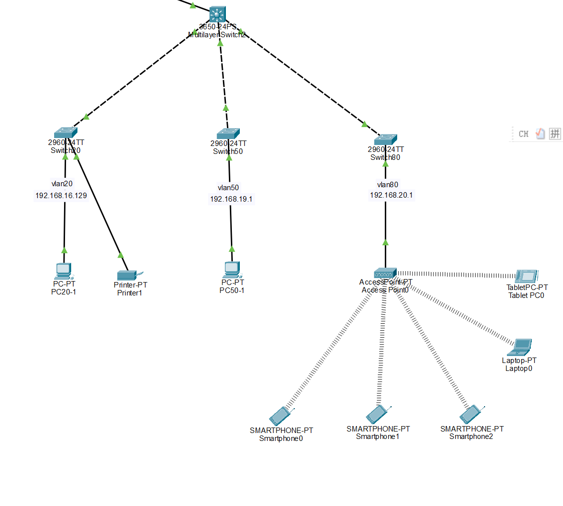
| 20 | Finance | 192.168.16.128/25 | 192.168.16.129 | MLS2 Vlan20 |
| 50 | Public-Relations | 192.168.19.0/25 | 192.168.19.1 | MLS2 Vlan50 |
| 80 | Wireless | 192.168.20.0/22 | 192.168.20.1 | MLS2 Vlan80 |
MLS2 端口规划
| GigabitEthernet1/0/1 | Switch20 G0/1 | Trunk | VLAN 20 |
| GigabitEthernet1/0/2 | Switch50 G0/1 | Trunk | VLAN 50 |
| GigabitEthernet1/0/3 | Switch80 G0/1 | Trunk | VLAN 80 |
| GigabitEthernet1/0/4 | Core Router G0/2 | 三层路由端口 | 192.168.19.169/30 |
MLS2拓扑图
MLS2中二层交换机代码
例如 SW20 是财务部,PC 接口属于 VLAN20:
enable
configure terminal
vlan 20
name FINANCE
! PC 所接的端口
interface fastEthernet 0/1
switchport mode access
switchport access vlan 20
spanning–tree portfast
! 上联到 MLS1 的端口
interface gigabitEthernet 0/1
switchport mode trunk
switchport trunk allowed vlan 20
end
write memory
例如 SW50 是公共关系部,PC 接口属于 VLAN50:
enable
configure terminal
vlan 50
name PUBLIC_RELATIONS
! PC 所接的端口
interface fastEthernet 0/1
switchport mode access
switchport access vlan 50
spanning–tree portfast
! 上联到 MLS1 的端口
interface gigabitEthernet 0/1
switchport mode trunk
switchport trunk allowed vlan 50
end
write memory
例如 SW80 是无线网络,PC 接口属于 VLAN80:
enable
configure terminal
vlan 80
name WIRELESS
! PC 所接的端口
interface fastEthernet 0/1
switchport mode access
switchport access vlan 80
spanning–tree portfast
! 上联到 MLS1 的端口
interface gigabitEthernet 0/1
switchport mode trunk
switchport trunk allowed vlan 80
end
write memory
MLS2(三层交换机 2)配置
负责 VLAN 20、50、80:
enable
configure terminal
! 开启三层交换和 VLAN 间路由
ip routing
! 创建 VLAN
vlan 20
name FINANCE
vlan 50
name PUBLIC_RELATIONS
vlan 80
name WIRELESS
! VLAN 20:财务部
interface vlan 20
ip address 192.168.16.129 255.255.255.128
no shutdown
! VLAN 50:公共关系部
interface vlan 50
ip address 192.168.19.1 255.255.255.128
no shutdown
! VLAN 80:无线网络
interface vlan 80
ip address 192.168.20.1 255.255.252.0
no shutdown
end
write memory
MLS2(三层交换机)上,把连接各二层交换机的物理接口设置为 Trunk。
enable
configure terminal
! 连接 SW20:只传递 VLAN 20
interface gigabitEthernet 1/0/1
switchport mode trunk
switchport trunk allowed vlan 20
exit
! 连接 SW50:只传递 VLAN 50
interface gigabitEthernet 1/0/2
switchport mode trunk
switchport trunk allowed vlan 50
exit
! 连接 SW80:只传递 VLAN 80
interface gigabitEthernet 1/0/3
switchport mode trunk
switchport trunk allowed vlan 80
exit
! 连接 SW70:只传递 VLAN 70
interface gigabitEthernet 1/0/4
switchport mode trunk
switchport trunk allowed vlan 70
exit
end
write memory
MLS2(三层交换机)上,把连接CoreRouter的物理接口设置ip地址
enable
configure terminal
! 连接 Core Router G0/2 的三层路由端口
interface gigabitEthernet 1/0/4
description TO_CORE_ROUTER_G0/2
no switchport
ip address 192.168.19.169 255.255.255.252
no shutdown
end
write memory
MLS2(三层交换机)上,建立OSPF 。
在 MLS2 输入:
enable
configure terminal
! 开启三层交换功能
ip routing
! ==================================
! MLS2 连接 Core Router 的三层接口
! ==================================
interface gigabitEthernet 1/0/4
description TO_CORE_ROUTER_G0/2
no switchport
ip address 192.168.19.169 255.255.255.252
no shutdown
exit
! ==================================
! 配置 OSPF
! ==================================
router ospf 1
! MLS2 的唯一 OSPF Router ID
router–id 3.3.3.3
! 默认让所有接口不建立 OSPF 邻居
passive–interface default
! 只有连接 Core 的接口允许建立 OSPF 邻居
no passive–interface gigabitEthernet 1/0/4
! Core ↔ MLS2 的三层互联链路
network 192.168.19.168 0.0.0.3 area 0
! VLAN 20:财务部
network 192.168.16.128 0.0.0.127 area 0
! VLAN 50:公共关系部
network 192.168.19.0 0.0.0.127 area 0
! VLAN 80:无线网络
network 192.168.20.0 0.0.3.255 area 0
end
write memory
Core Router 设计
三层链路与地址规划
| Core Router – ASA | Core Router G0/0 192.168.19.174/30 | ASA inside 192.168.19.173/30 | 192.168.19.172/30 |
| Core Router – MLS1 | Core Router G0/1 192.168.19.166/30 | MLS1 G1/0/5 192.168.19.165/30 | 192.168.19.164/30 |
| Core Router – MLS2 | Core Router G0/2 192.168.19.170/30 | MLS2 G1/0/4 192.168.19.169/30 | 192.168.19.168/30 |
连线
| Core Router | GigabitEthernet0/0 | ASA-Firewall | Ethernet0/1 | eStraightThrough |
| Core Router | GigabitEthernet0/1 | MLS1 | GigabitEthernet1/0/5 | eStraightThrough |
| Core Router | GigabitEthernet0/2 | MLS2 | GigabitEthernet1/0/4 | eStraightThrough |
Core Router 接口规划
| GigabitEthernet0/0 | ASA inside | 192.168.19.174/30 | 192.168.19.173/30 | 连接防火墙、访问外网 | outside |
| GigabitEthernet0/1 | MLS1 G1/0/5 | 192.168.19.166/30 | 192.168.19.165/30 | 连接 VLAN 10、40、60、70 | inside |
| GigabitEthernet0/2 | MLS2 G1/0/4 | 192.168.19.170/30 | 192.168.19.169/30 | 连接 VLAN 20、50、80 | inside |
Core Router 路由与 NAT 规划
| OSPF 进程号 | router ospf 1 | 与 MLS1、MLS2 动态交换路由 |
| Core Router ID | 1.1.1.1 | Core Router 的唯一 OSPF 标识 |
| OSPF Area | Area 0 | OSPF 骨干区域 |
| MLS1 互联网段 | 192.168.19.164/30 | 与 MLS1 建立 OSPF 邻居 |
| MLS2 互联网段 | 192.168.19.168/30 | 与 MLS2 建立 OSPF 邻居 |
| 默认路由 | 0.0.0.0/0 → 192.168.19.173 | 未知流量交给 ASA |
| NAT ACL | 192.168.16.0 0.0.15.255 | 允许内网 192.168.16.0/20 出网 |
| PAT 接口 | GigabitEthernet0/0 | 所有内网主机共用 192.168.19.174 出网 |
Core Router 可学习到的业务网段
| MLS1 | 10 | Administration-HR | 192.168.16.0/25 | 192.168.16.1 |
| MLS2 | 20 | Finance | 192.168.16.128/25 | 192.168.16.129 |
| MLS1 | 40 | Sales-Marketing | 192.168.17.0/24 | 192.168.17.1 |
| MLS1 | 60 | IT-Communications | 192.168.18.0/24 | 192.168.18.1 |
| MLS2 | 50 | Public-Relations | 192.168.19.0/25 | 192.168.19.1 |
| MLS1 | 70 | Server-Room | 192.168.19.128/27 | 192.168.19.129 |
| MLS2 | 80 | Wireless | 192.168.20.0/22 | 192.168.20.1 |
Core Router配置
enable
configure terminal
! 设置核心路由器名称
hostname CORE–Router
! ==============================
! G0/0:连接 ASA
! ==============================
interface GigabitEthernet0/0
description TO_ASA
! Core Router:192.168.19.174/30
! ASA inside:192.168.19.173/30
ip address 192.168.19.174 255.255.255.252
ip nat outside
no shutdown
exit
! ==============================
! G0/1:连接 MLS1
! ==============================
interface GigabitEthernet0/1
description TO_MLS1
! Core Router:192.168.19.166/30
! MLS1:192.168.19.165/30
ip address 192.168.19.166 255.255.255.252
ip nat inside
no shutdown
exit
! ==============================
! G0/2:连接 MLS2
! ==============================
interface GigabitEthernet0/2
description TO_MLS2
! Core Router:192.168.19.170/30
! MLS2:192.168.19.169/30
ip address 192.168.19.170 255.255.255.252
ip nat inside
no shutdown
exit
! ==============================
! 配置 OSPF
! ==============================
router ospf 1
router–id 1.1.1.1
network 192.168.19.164 0.0.0.3 area 0
network 192.168.19.168 0.0.0.3 area 0
default–information originate
exit
! ==============================
! NAT 使用的 ACL
! 允许 192.168.16.0 ~ 192.168.31.255
! ==============================
access–list 10 permit 192.168.16.0 0.0.15.255
! 配置 PAT:内网设备共用 G0/0 地址出网
ip nat inside source list 10 interface GigabitEthernet0/0 overload
! 默认路由:未知流量交给 ASA
ip route 0.0.0.0 0.0.0.0 192.168.19.173
end
write memory
在Core Router中确认配置生效
1.show ip interface brief
2.show ip route
3.show ip ospf neighbor
4.show ip protocols
5.show ip nat statistics
6.show startup–config
ASA三层链路与地址规划
| ASA – Core Router | ASA inside 192.168.19.173/30 | Core Router G0/0 192.168.19.174/30 | 192.168.19.172/30 |
| ASA – ISP Router | ASA outside 193.168.16.2/30 | ISP Router 193.168.16.1/30 | 193.168.16.0/30 |
连线
| ASA-Firewall | Ethernet0/1 | Core Router | GigabitEthernet0/0 | eStraightThrough |
| ASA-Firewall | Ethernet0/0 | ISP Router | GigabitEthernet0/0 | eStraightThrough |
ASA 接口规划
| Vlan1 | Ethernet0/1 | inside | 100 | 192.168.19.173/30 | Core Router G0/0 192.168.19.174 | 接收公司内网流量 |
| Vlan2 | Ethernet0/0 | outside | 0 | 193.168.16.2/30 | ISP Router G0/0 193.168.16.1 | 连接 ISP 与外部网络 |
ASA 路由、NAT 与安全策略
| 默认路由 | route outside 0.0.0.0 0.0.0.0 193.168.16.1 | 所有未知流量发送给 ISP Router |
| NAT 对象 | CORE_PAT_IP | 表示 Core Router NAT 后的地址 192.168.19.174 |
| ASA PAT | nat (inside,outside) dynamic interface | 将 192.168.19.174 转换为 ASA outside 地址 193.168.16.2 出网 |
| ICMP 检查 | inspect icmp | 允许内网主动 Ping 外网时,Echo Reply 正确返回 |
| 全局策略 | service-policy global_policy global | 将 ICMP 检查策略应用到 ASA 全局 |
| 外网 ACL | access-group OUTSIDE_IN in interface outside | 将 OUTSIDE_IN ACL 应用到 outside 入方向 |
| ICMP ACL | permit icmp any any echo-reply | 允许外网返回 ICMP Echo Reply 报文 |
| TCP ACL | permit tcp host 203.0.113.2 host 192.168.19.174 | 配置了来自 Web Server 的 TCP 放行规则 |
内网访问外网时的地址转换过程
| 内网主机发包 | 例如 192.168.16.10 | PC |
| 第一次 PAT | 192.168.16.10 → 192.168.19.174 | Core Router |
| 第二次 PAT | 192.168.19.174 → 193.168.16.2 | ASA-Firewall |
| 发往外网 | 源地址为 193.168.16.2 | ISP Router / Internet |
ASA配置
enable
configure terminal
! 设置 ASA 名称
hostname ASA–Firewall
! ==============================
! Inside:连接 Core Router
! ASA:192.168.19.173/30
! Core:192.168.19.174/30
! ==============================
interface Vlan1
nameif inside
security–level 100
ip address 192.168.19.173 255.255.255.252
no shutdown
exit
! ==============================
! Outside:连接 ISP Router
! ASA:193.168.16.2/30
! ISP:193.168.16.1/30
! ==============================
interface Vlan2
nameif outside
security–level 0
no ip address dhcp setroute
ip address 193.168.16.2 255.255.255.252
no shutdown
exit
! E0/0:连接 ISP,加入 outside 的 VLAN 2
interface Ethernet0/0
switchport access vlan 2
no shutdown
exit
! E0/1:连接 Core Router,加入 inside 的 VLAN 1
interface Ethernet0/1
switchport access vlan 1
no shutdown
exit
! 默认路由:未知流量发往 ISP
route outside 0.0.0.0 0.0.0.0 193.168.16.1
! ==============================
! ASA PAT
! Core PAT 后的源地址 .174
! 再转换为 ASA outside 地址 .2
! ==============================
object network CORE_PAT_IP
host 192.168.19.174
nat (inside,outside) dynamic interface
exit
! ==============================
! ICMP 检查策略
! 允许内网 ping 的 Echo Reply 正确返回
! ==============================+++++++++++++++++++++++++++
configure terminal
class–map inspection_default
match default–inspection–traffic
exit
configure terminal
policy–map global_policy
class inspection_default
inspect icmp
exit
! 此处已回到 ASA(config)# 全局配置模式
configure terminal
service–policy global_policy global
end
write memory
enable
configure terminal
access–list OUTSIDE_IN extended permit icmp any any echo–reply
access–group OUTSIDE_IN in interface outside
end
write memory
enable
configure terminal
access–list OUTSIDE_IN extended permit tcp host 203.0.113.2 host 192.168.19.174
end
write memory
ASA–Firewall#configure terminal
ASA–Firewall(config)#service–policy global_policy global
WARNING: Policy map global_policy is already configured as a service policy
ASA–Firewall(config)#end
ASA–Firewall#write memory
确认ASA配置生效
注意:你最后配置的 TCP ACL 虽然允许 203.0.113.2 访问 192.168.19.174,
但 .174 使用的是动态 PAT,不能用于稳定的外网主动访问内网服务。
若以后要让外网访问内网服务器,需要额外配置静态 NAT 或端口映射。
a.验证接口、VLAN 和安全域
enable
show interface ip brief
show nameif
show running–config interface Ethernet0/0
show running–config interface Ethernet0/1
正确时应确认:
Vlan1 = 192.168.19.173 = inside = security–level 100
Vlan2 = 193.168.16.2 = outside = security–level 0
Ethernet0/0 = access vlan 2
Ethernet0/1 = access vlan 1
show interface ip brief 中,Vlan1、Vlan2、Ethernet0/0、Ethernet0/1 都是:up up
b.验证 ASA 到 Core 和 ISP 的直连链路
192.168.19.174 = Core Router G0/0
193.168.16.1 = ISP Router
ping 192.168.19.174
ping 193.168.16.1
c.验证默认路由
show route
C 192.168.19.172 255.255.255.252 is directly connected, inside
C 193.168.16.0 255.255.255.252 is directly connected, outside
S* 0.0.0.0 0.0.0.0 [1/0] via 193.168.16.1, outside
最关键的是:S* 0.0.0.0/0 → 193.168.16.1, outside
这表示未知的外网流量会被 ASA 发给 ISP Router。
d.验证 ASA NAT 规则是否存在
show nat
Auto NAT Policies (Section 2)
1 (inside) to (outside) source dynamic CORE_PAT_IP interface
这代表:inside 源地址 192.168.19.174会被动态转换为 ASA outside 地址 193.168.16.2
e.验证 ICMP 检查策略已应用
show service–policy
应看到类似:
Global policy:
Service–policy: global_policy
Class–map: inspection_default
Inspect: icmp
这表示:inspect icmp已经作为全局策略生效,内网发出的 ping 回包可以正常返回。
f.最重要:用内网 PC 产生真实出网流量
在任意内网 PC 上执行,例如 VLAN 10 的 PC:
ping 192.168.16.1
ping 203.0.113.2
然后立刻到 ASA 输入:
show xlate
show nat
show conn
show service–policy
show xlate 中应看到与下列含义相同的 NAT 映射:
Inside local: 192.168.19.174
Inside global: 193.168.16.2
注意:ASA 上看不到原始 PC 的 192.168.16.x,这是正常的;因为 Core 已先把它转换为 .174。
此时 show nat 的计数应增加:
translate_hits > 0
untranslate_hits > 0
translate_hits 增加:ASA 已把 .174 转为 .16.2。
untranslate_hits 增加:外网返回流量已被 ASA 转回 .174。
g.验证配置已保存
show startup–config
ISP-Router 三层链路与地址规划
| ISP Router – ASA | ISP Router G0/0 193.168.16.1/30 | ASA outside 193.168.16.2/30 | 193.168.16.0/30 |
| ISP Router – Web Server | ISP Router G0/1 203.0.113.1/24 | Web Server 203.0.113.2/24 | 203.0.113.0/24 |
连线
| ISP-Router | GigabitEthernet0/0 | ASA-Firewall | Ethernet0/0 | eStraightThrough |
| ISP-Router | GigabitEthernet0/1 | Web Server | FastEthernet0 | eStraightThrough |
ISP Router 接口规划
| GigabitEthernet0/0 | TO_ASA_OUTSIDE | 193.168.16.1 | 255.255.255.252 | ASA outside 193.168.16.2 | 模拟 ISP,与 ASA 外网接口互联 |
| GigabitEthernet0/1 | TO_WEB_SERVER | 203.0.113.1 | 255.255.255.0 | Web Server 203.0.113.2 | 模拟公网服务器所在网段的网关 |
公网 Web Server 地址规划
| Web Server | 203.0.113.2 | 255.255.255.0 | 203.0.113.1 | 203.0.113.0/24 |
在 ISP Router 输入:
enable
configure terminal
! 设置 ISP 路由器名称
hostname ISP–Router
! ==============================
! G0/0:连接 ASA outside
! ==============================
interface GigabitEthernet0/0
description TO_ASA_OUTSIDE
ip address 193.168.16.1 255.255.255.252
no shutdown
exit
! ==============================
! G0/1:连接模拟公网 Web Server
! ==============================
interface GigabitEthernet0/1
description TO_WEB_SERVER
ip address 203.0.113.1 255.255.255.0
no shutdown
exit
end
write memory
Web Server 的 Desktop → IP Configuration 设置:
IP Address: 203.0.113.2
Subnet Mask: 255.255.255.0
Default Gateway: 203.0.113.1
SW70:将两台服务器端口加入 VLAN 70
DHCP Server配置静态 IP
Desktop → IP Configuration → Static
填写:
IP Address: 192.168.19.130
Subnet Mask: 255.255.255.224
Default Gateway: 192.168.19.129
DNS Server: 192.168.19.131
点击 Add ,建立其他 VLAN 的 Pool。
| VLAN10_ADMIN_HR | 10 | 192.168.16.1 | 192.168.19.131 | 192.168.16.10 | 255.255.255.128 | 90 |
| VLAN20_FINANCE | 20 | 192.168.16.129 | 192.168.19.131 | 192.168.16.140 | 255.255.255.128 | 90 |
| VLAN40_SALES | 40 | 192.168.17.1 | 192.168.19.131 | 192.168.17.10 | 255.255.255.0 | 200 |
| VLAN50_PR | 50 | 192.168.19.1 | 192.168.19.131 | 192.168.19.10 | 255.255.255.128 | 90 |
| VLAN60_IT | 60 | 192.168.18.1 | 192.168.19.131 | 192.168.18.10 | 255.255.255.0 | 200 |
| VLAN80_WIRELESS | 80 | 192.168.20.1 | 192.168.19.131 | 192.168.20.10 | 255.255.252.0 | 1000 |
不需要为 VLAN 70 创建 Pool,因为:
DHCP Server:192.168.19.130(静态)
DNS Server: 192.168.19.131(静态)
它们自己不应该通过 DHCP 获取地址。
DNS Server:配置静态 IP
Desktop → IP Configuration → Static
填写:
IP Address: 192.168.19.131
Subnet Mask: 255.255.255.224
Default Gateway: 192.168.19.129
DNS Server: 192.168.19.131
然后进入:
Services → DNS → On
添加 A 记录:
NameAddress
www.test.com203.0.113.2
点击 Add。
将两台服务器所接的端口属于 VLAN 70
enable
configure terminal
! DHCP Server 与 DNS Server 的端口都加入 VLAN 70
interface range fastEthernet 0/1–2
switchport mode access
switchport access vlan 70
spanning–tree portfast
no shutdown
exit
end
write memory
将所有客户端 VLAN 的 DHCP Relay 指向 DHCP Server .130
MLS1:VLAN 10、40、60 配置 DHCP Relay
enable
configure terminal
! DHCP Server:192.168.19.130
! DNS Server:192.168.19.131
! ==============================
! VLAN 10:行政与人力资源部
! ==============================
interface vlan 10
no ip helper–address 192.168.19.170
no ip helper–address 192.168.19.131
ip helper–address 192.168.19.130
exit
! ==============================
! VLAN 40:销售与市场部
! ==============================
interface vlan 40
no ip helper–address 192.168.19.170
no ip helper–address 192.168.19.131
ip helper–address 192.168.19.130
exit
! ==============================
! VLAN 60:IT 与通信部
! ==============================
interface vlan 60
no ip helper–address 192.168.19.170
no ip helper–address 192.168.19.131
ip helper–address 192.168.19.130
exit
end
write memory
MLS2:VLAN 20、50、80 配置 DHCP Relay
enable
configure terminal
! DHCP Server:192.168.19.130
! DNS Server:192.168.19.131
! ==============================
! VLAN 20:财务部
! ==============================
interface vlan 20
no ip helper–address 192.168.19.170
no ip helper–address 192.168.19.131
ip helper–address 192.168.19.130
exit
! ==============================
! VLAN 50:公共关系部
! ==============================
interface vlan 50
no ip helper–address 192.168.19.170
no ip helper–address 192.168.19.131
ip helper–address 192.168.19.130
exit
! ==============================
! VLAN 80:无线网络
! ==============================
interface vlan 80
no ip helper–address 192.168.19.170
no ip helper–address 192.168.19.131
ip helper–address 192.168.19.130
exit
end
write memory
VLAN 70 不需要 ip helper–address,因为 DHCP Server 就在 VLAN 70 内。
vlan80操作
AP 的网线连接方式:
Switch80 Fa0/1
↓ 使用 Copper Straight–Through
AccessPoint–PT 的 Ethernet / Port 0
Port 0 = 用网线连接 Switch6 的接口
Port 1 = 无线 Wi–Fi 接口
先直接在你当前的 Port 1 页面配置 Wi‑Fi:
把 SSID 从 Default 改为:Apple–WiFi
在 Authentication 中点击:WPA2–PSK
此时右侧的 PSK Pass Phrase 输入框会解除灰色状态,输入:pple@2026
如果要求选择加密方式,选择:AES
保持右上角:Port Status:On
如果 Settings 和 Port 0 中都没有 IP 地址输入框,说明你这个 Packet Tracer 的 AccessPoint–PT 是一个纯二层 AP 模型。此时不需要给 AP 配置 .20.2,它仍然可以正常工作,只负责把:交换机 VLAN 80↔无线客户端连接起来。
添加pc的时候记得将pc的网口设置为无线
添加打印机
Connections → Copper Straight–Through连接:Printer FastEthernet0 → 接入交换机 Fa0/x
配置交换机端口
假设打印机接在 Fa0/24:
enable
configure terminal
interface FastEthernet0/24
switchport mode access
switchport access vlan 10
no shutdown
end
write memory
配置打印机 IP
总拓扑


![【LMP】规范精讲[6]: 从陌生到互信——安全简单配对(SSP)的四步握手-网硕互联帮助中心](https://www.wsisp.com/helps/wp-content/uploads/2026/10/20261024191700-6add042c4303e-220x150.png)


评论前必须登录!
注册