 网硕互联帮助中心
-
项目介绍
某实验中学需要组建校园网,学校有教学楼、办公楼、实验楼、图书馆、食堂与宿舍等区域,现需要将他们相互连接组建成一套校园网网络,彼此之间可以相互访问,实现资源共享,可访问校园网数据中心服务器,还可以访问互联网进行学习办公。
-
规划设计
网络拓扑规划
根据学校整体划分成核心层、汇聚层与接入层。核心层采用双机热备,汇聚层通过双链路链接到主备核心。学校内部互联网之间通过出口路由器进行连接,核心与出口路由之间部署一台防火墙做网络安全防御。具体网络拓扑规划如下:
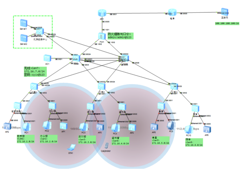
图2-1 网络规划拓扑图
技术方案规划
IP地址规划
根据学校规模,规划在藤县实验中学使用172.16.0.0/16的IP网段,再划分子网,每个子网使用最后一个IP地址作为本网段的通信网关。IP地址具体规划如下:
藤县实验中学业务IP地址规划:
|
序号 |
名称 |
IP |
子网掩码 |
VLAN |
网关 |
备注 |
|
1 |
教学楼 |
172.16.1.0 |
255.255.255.0 |
1 |
172.16.1.254 |
|
|
2 |
办公楼 |
172.16.2.0 |
255.255.255.0 |
2 |
172.16.2.254 |
|
|
3 |
实训楼 |
172.16.3.0 |
255.255.255.0 |
3 |
172.16.3.254 |
|
|
4 |
图书馆 |
172.16.4.0 |
255.255.255.0 |
4 |
172.16.4.254 |
|
|
5 |
食堂 |
172.16.5.0 |
255.255.255.0 |
5 |
172.16.5.254 |
|
|
6 |
宿舍 |
172.16.6.0 |
255.255.255.0 |
6 |
172.16.6.254 |
|
|
7 |
无线网络 |
172.16.7.0 |
255.255.255.0 |
8 |
172.16.7.254 |
|
|
8 |
数据中心 |
172.16.100.0 |
255.255.255.0 |
100 |
172.16.100.254 |
|
-
配置实施
根据学校网络拓扑,技术协议规划,使用华为ENSP模拟器对该学校网络进行模拟仿真配置,各个网络设备具体配置如下:
路由器R1
sysname AR1 //修改设备名称
interface GigabitEthernet0/0/1 //进入端口g0/0/1
ip address 8.8.8.2 255.255.255.0 //配置接口IP
quit //退出
interface GigabitEthernet0/0/0
ip address 172.16.200.5 255.255.255.252
quit
ip route-static 0.0.0.0 0 8.8.8.1 //配置默认路由
ospf 1 //创建OSPF进程1并进入配置模式
area 0.0.0.0 //配置区域为0
network 172.16.200.0 0.0.0.3 //发布路由网段
acl number 3001 //创建高级ACL3001
rule 1 permit ip //创建策略1,允许所有IP
quit
interface GigabitEthernet0/0/1 //进入端口G0/0/1
nat outbound 3001 //将ACL3001中策略匹配的IP做NAT转换
quit
防火墙FW1
防火墙主要用户校园网内部网络安全防御,允许内部访问外部,禁止互联网访问校园网,与其它设备之间运行OSPF路由协议。
interface GigabitEthernet1/0/1 //进入端口g1/0/0
ip address 172.16.200.2 255.255.255.252 //配置接口IP
quit
interface GigabitEthernet1/0/1
ip address 172.16.200.5 255.255.255.252
service-manage all permit
quit
interface GigabitEthernet1/0/2
undo shutdown
ip address 172.16.200.9 255.255.255.252
service-manage all permit
quit
quit
firewall zone trust //创建内部区域trust
add interface GigabitEthernet1/0/2 //将端口1/0/2加入
add interface GigabitEthernet1/0/3 //将端口1/0/3加入
quit
firewall zone untrust //创建外部区域untrust
add interface GigabitEthernet1/0/1
quit
ospf 1
area 0.0.0.0
network 172.16.200.4 0.0.0.3
network 172.16.200.8 0.0.0.3
network 172.16.200.0 0.0.0.3
quit
quit
security-policy //进入安全策略配置模式
rule name 1 //创建安全规则1
source-zone trust //源区域为内部
destination-zone untrust //目的区域为外部
action permit //允许访问
quit
quit
核心交换机1
核心交换机1与2运行VRRP双机热备,使用双链路端口聚合连接,与防火墙运行OSPF,汇聚运行MSTP与VLAN Trunk。
sysname Core1
vlan batch 2 to 7 100 //创建业务VLAN
stp region-configuration //进入STP配置模式
instance 1 vlan 1 to 7 //创建实例1,将VLAN加入
active region-configuration //激活STP配置
stp instance 1 root primary //配置为根桥
Vlan 200 //创建路由接口VLAN
quit
interface Vlanif200 //创建VLANIF200
ip address 172.16.200.6 255.255.255.252 //配置接口IP
quit
interface GigabitEthernet0/0/24 //进入端口G0/0/24
port link-type access //配置成ACCESS模式
port default vlan 200 //将端口加入到VLAN200
quit
interface Vlanif1 //创建业务VLANIF1
ip address 172.16.1.252 255.255.255.0 //配置接口IP
vrrp vrid 1 virtual-ip 172.16.1.254 //配置VRRP虚拟IP
vrrp vrid 1 priority 180 //配置VRRP的优先级为180
vrrp vrid 1 track interface GigabitEthernet0/0/24 reduced 120 //配置与上端联动,发生故障VRRP的优先级下降120变成60
quit
interface Vlanif2
ip address 172.16.2.252 255.255.255.0
vrrp vrid 2 virtual-ip 172.16.2.254
vrrp vrid 2 priority 180
vrrp vrid 2 track interface GigabitEthernet0/0/24 reduced 120
quit
interface Vlanif3
ip address 172.16.3.252 255.255.255.0
vrrp vrid 3 virtual-ip 172.16.3.254
vrrp vrid 3 priority 180
vrrp vrid 3 track interface GigabitEthernet0/0/24 reduced 120
quit
interface Vlanif4
ip address 172.16.4.252 255.255.255.0
vrrp vrid 4 virtual-ip 172.16.4.254
vrrp vrid 4 priority 180
vrrp vrid 4 track interface GigabitEthernet0/0/24 reduced 120
quit
interface Vlanif5
ip address 172.16.5.252 255.255.255.0
vrrp vrid 5 virtual-ip 172.16.5.254
vrrp vrid 5 priority 180
vrrp vrid 5 track interface GigabitEthernet0/0/24 reduced 120
quit
interface Vlanif6
ip address 172.16.6.252 255.255.255.0
vrrp vrid 6 virtual-ip 172.16.6.254
vrrp vrid 6 priority 180
vrrp vrid 6 track interface GigabitEthernet0/0/24 reduced 120
quit
interface Vlanif7
ip address 172.16.7.252 255.255.255.0
vrrp vrid 7 virtual-ip 172.16.7.254
vrrp vrid 7 priority 180
vrrp vrid 7 track interface GigabitEthernet0/0/24 reduced 120
quit
interface Vlanif100
ip address 172.16.100.252 255.255.255.0
vrrp vrid 100 virtual-ip 172.16.100.254
vrrp vrid 100 priority 180
vrrp vrid 100 track interface GigabitEthernet0/0/24 reduced 120
quit
ospf 1
area 0.0.0.0
network 172.16.200.4 0.0.0.3
network 172.16.1.0 0.0.0.255
network 172.16.2.0 0.0.0.255
network 172.16.3.0 0.0.0.255
network 172.16.4.0 0.0.0.255
network 172.16.5.0 0.0.0.255
network 172.16.6.0 0.0.0.255
network 172.16.7.0 0.0.0.255
network 172.16.100.0 0.0.0.255
quit
quit
dhcp enable //开启DHCP服务
ip pool vlan7 //创建地址池7
gateway-list 172.16.7.254 //配置网关
network 172.16.7.0 mask 255.255.255.0 //配置分配网段
dns-list 114.114.114.114 8.8.8.8 //配置分配DNS
excluded-ip-address 172.16.7.250 172.16.7.253 //排除250-253不做分配
quit
interface Vlanif7 //进入VLANFI7
dhcp select global //选择为全局地址池。
quit
interface Eth-Trunk1 //创建聚合组1
port link-type trunk //配置成Trunk模式
port trunk allow-pass vlan 1 to 7 100 //允许VLAN通过
quit
interface GigabitEthernet0/0/21 //进入端口21
eth-trunk 1 //加入到聚合组1
quit
interface GigabitEthernet0/0/22
eth-trunk 1
quit
port-group 1 //创建端口组1
group-member GigabitEthernet 0/0/1 to GigabitEthernet 0/0/10 //将端口1-10加入
port link-type trunk //配置成Trunk
port trunk allow-pass vlan 2 to 7 100 //允许VLAN通过
quit
核心交换机2
核心交换机备配置流程方法与核心主一致,按照实际情况修改IP地址、VRRP优先级,MSTP生成树与发布路由。
sysname Core2
vlan 200
vlan 100
vlan batch 2 to 7
stp region-configuration
instance 1 vlan 1 to 7
active region-configuration
stp instance 1 root secondary
interface Vlanif200
ip address 172.16.200.10 255.255.255.252
quit
interface GigabitEthernet0/0/24
port link-type access
port default vlan 200
quit
interface Vlanif1
ip address 172.16.1.253 255.255.255.0
vrrp vrid 1 virtual-ip 172.16.1.254
vrrp vrid 1 priority 80
quit
interface Vlanif2
ip address 172.16.2.253 255.255.255.0
vrrp vrid 2 virtual-ip 172.16.2.254
vrrp vrid 2 priority 80
quit
interface Vlanif3
ip address 172.16.3.253 255.255.255.0
vrrp vrid 3 virtual-ip 172.16.3.254
vrrp vrid 3 priority 80
quit
interface Vlanif4
ip address 172.16.4.253 255.255.255.0
vrrp vrid 4 virtual-ip 172.16.4.254
vrrp vrid 4 priority 80
quit
interface Vlanif5
ip address 172.16.5.253 255.255.255.0
vrrp vrid 5 virtual-ip 172.16.5.254
vrrp vrid 5 priority 80
quit
interface Vlanif6
ip address 172.16.6.253 255.255.255.0
vrrp vrid 6 virtual-ip 172.16.6.254
vrrp vrid 6 priority 80
quit
interface Vlanif7
ip address 172.16.7.253 255.255.255.0
vrrp vrid 7 virtual-ip 172.16.7.254
vrrp vrid 7 priority 80
quit
interface Vlanif100
ip address 172.16.100.253 255.255.255.0
vrrp vrid 100 virtual-ip 172.16.100.254
vrrp vrid 100 priority 80
quit
ospf 1
area 0.0.0.0
network 172.16.200.8 0.0.0.3
network 172.16.1.0 0.0.0.255
network 172.16.2.0 0.0.0.255
network 172.16.3.0 0.0.0.255
network 172.16.4.0 0.0.0.255
network 172.16.5.0 0.0.0.255
network 172.16.6.0 0.0.0.255
network 172.16.7.0 0.0.0.255
network 172.16.100.0 0.0.0.255
quit
quit
ip route-static 0.0.0.0 0.0.0.0 172.16.200.5
dhcp enable
ip pool vlan7
gateway-list 172.16.7.254
network 172.16.7.0 mask 255.255.255.0
dns-list 114.114.114.114 8.8.8.8
excluded-ip-address 172.16.7.250 172.16.7.253
quit
interface Vlanif7
dhcp select global
quit
interface Eth-Trunk1
port link-type trunk
port trunk allow-pass vlan 1 to 7 100
quit
interface GigabitEthernet0/0/21
eth-trunk 1
quit
interface GigabitEthernet0/0/22
eth-trunk 1
quit
port-group 1
group-member GigabitEthernet 0/0/1 to GigabitEthernet 0/0/10
port link-type trunk
port trunk allow-pass vlan 2 to 7 100
quit
汇集交换机
汇聚交换机用于接入交换机级联汇聚使用,所有端口配置为Trunk模式。各个汇聚交换机配置都一样。
配置命令:
vlan batch 2 to 7
stp region-configuration
instance 1 vlan 1 to 7
active region-configuration
quit
port-group 1
group-member GigabitEthernet 0/0/1 to GigabitEthernet 0/0/24
port link-type trunk
port trunk allow-pass vlan all
quit
服务器接入
数据中心交换机用于服务器的网络接入使用,与主备核心运行Trunk模式,连接服务器使用ACCESS模式。
vlan 100
quit
stp region-configuration
instance 1 vlan 100
active region-configuration
quit
interface GigabitEthernet0/0/24
port link-type trunk
port trunk allow-pass vlan all
quit
interface GigabitEthernet0/0/23
port link-type trunk
port trunk allow-pass vlan all
quit
port-group 1
group-member GigabitEthernet 0/0/1 to GigabitEthernet 0/0/20
port link-type access
port default vlan 100
quit
接入交换机
终端设备接入交换机连接客户端配置成ACCESS模式,连接上端汇聚为Trunk模式,各个接入交换机配置原理一样,加入到不同VLAN中。连接AP的端口配置PVID VLAN为7
vlan batch 2 to 7
stp region-configuration
instance 1 vlan 1 to 7
active region-configuration
quit
interface GigabitEthernet0/0/1
port link-type trunk
port trunk allow-pass vlan all
quit
interface Ethernet0/0/1
port link-type access
port default vlan 1
quit
interface Ethernet0/0/2 //进入端口2
port link-type trunk //配置Trunk模式
port trunk allow-pass vlan all //允许VLAN通过
port trunk pvid vlan 7 //配置PVID的VLAN ID 为7
quit
vlan batch 2 to 7
stp region-configuration
instance 1 vlan 1 to 7
active region-configuration
quit
interface GigabitEthernet0/0/1
port link-type trunk
port trunk allow-pass vlan all
quit
interface Ethernet0/0/1
port link-type access
port default vlan 2
quit
interface Ethernet0/0/2
port link-type trunk
port trunk allow-pass vlan all
port trunk pvid vlan 7
quit
vlan batch 2 to 7
stp region-configuration
instance 1 vlan 1 to 7
active region-configuration
quit
interface GigabitEthernet0/0/1
port link-type trunk
port trunk allow-pass vlan all
quit
interface Ethernet0/0/1
port link-type access
port default vlan 3
quit
interface Ethernet0/0/2
port link-type trunk
port trunk allow-pass vlan all
port trunk pvid vlan 7
quit
vlan batch 2 to 7
stp region-configuration
instance 1 vlan 1 to 7
active region-configuration
quit
interface GigabitEthernet0/0/1
port link-type trunk
port trunk allow-pass vlan all
quit
interface Ethernet0/0/1
port link-type access
port default vlan 4
quit
interface Ethernet0/0/2
port link-type trunk
port trunk allow-pass vlan all
port trunk pvid vlan 7
quit
vlan batch 2 to 7
stp region-configuration
instance 1 vlan 1 to 7
active region-configuration
quit
interface GigabitEthernet0/0/1
port link-type trunk
port trunk allow-pass vlan all
quit
interface Ethernet0/0/1
port link-type access
port default vlan 5
quit
interface Ethernet0/0/2
port link-type trunk
port trunk allow-pass vlan all
port trunk pvid vlan 7
quit
vlan batch 2 to 7
stp region-configuration
instance 1 vlan 1 to 7
active region-configuration
quit
interface GigabitEthernet0/0/1
port link-type trunk
port trunk allow-pass vlan all
quit
interface Ethernet0/0/1
port link-type access
port default vlan 6
quit
interface Ethernet0/0/2
port link-type trunk
port trunk allow-pass vlan all
port trunk pvid vlan 7
quit
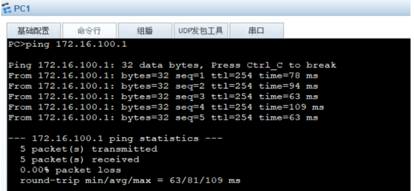
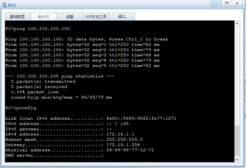
- 验证测试
1)教学楼访问数据中心


评论前必须登录!
注册