 网硕互联帮助中心
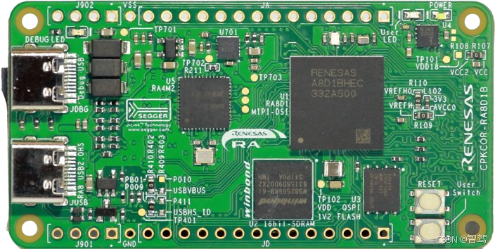
1. 摘要🪅
在上一篇中主要记录刚拿到测评板后,如何查找资料、如何搭建环境、如何调试等过程,本篇主要介绍如何在这个开发板上跑Zephyr,以及通过Zephyr自带的例程,如何测试核心板和扩展板的外设资源。欢迎大家收藏、转发,多多交流哈🤗😃🎉🪅📢 🏳️🌈🏳️🌈🏳️🌈🏳️🌈🏳️🌈🏳️🌈🏳️🌈🏳️🌈🏳️🌈🏳️🌈🏳️🌈🏳️🌈🏳️🌈🏳️🌈🏳️🌈🏳️🌈🏳️🌈🏳️🌈🏳️🌈🏳️🌈🏳️🌈🏳️🌈🏳️🌈🏳️🌈🏳️🌈🏳️🌈🏳️🌈🏳️🌈🏳️🌈🏳️🌈🏳️🌈🏳️🌈🏳️🌈🏳️🌈🏳️🌈🏳️🌈🏳️🌈🏳️🌈🏳️🌈🏳️🌈🏳️🌈🏳️🌈🏳️🌈🏳️🌈 🚀 ——评测系列跳转——🚀 【瑞萨RA8D1 LVGL/LWIP评测】一、开篇
2. Zephyr工程适配步骤
对Zephyr不太熟悉的小伙伴,可以先阅读下下面的几篇博客,然后再回过头来阅读本篇。
我们查看Zephyr的board支持列表,发现并没有支持CPKCOR-RA8D1B,那如何快速支持呢?要从0开始手写吗?当然不是。
我们可以参考EK-RA8D1,Zephyr是支持,EK-RA8D1和CPKCOR-RA8D1B的主控一致,完全可以“照抄”。
在zephyr\\boards\\renesas路径下,我们直接复制ek_ra8d1文件夹,改名为cpkcor_ra8d1b,然后修改里面的.dts、.yaml,Kconfig等文件的名字,如下图: 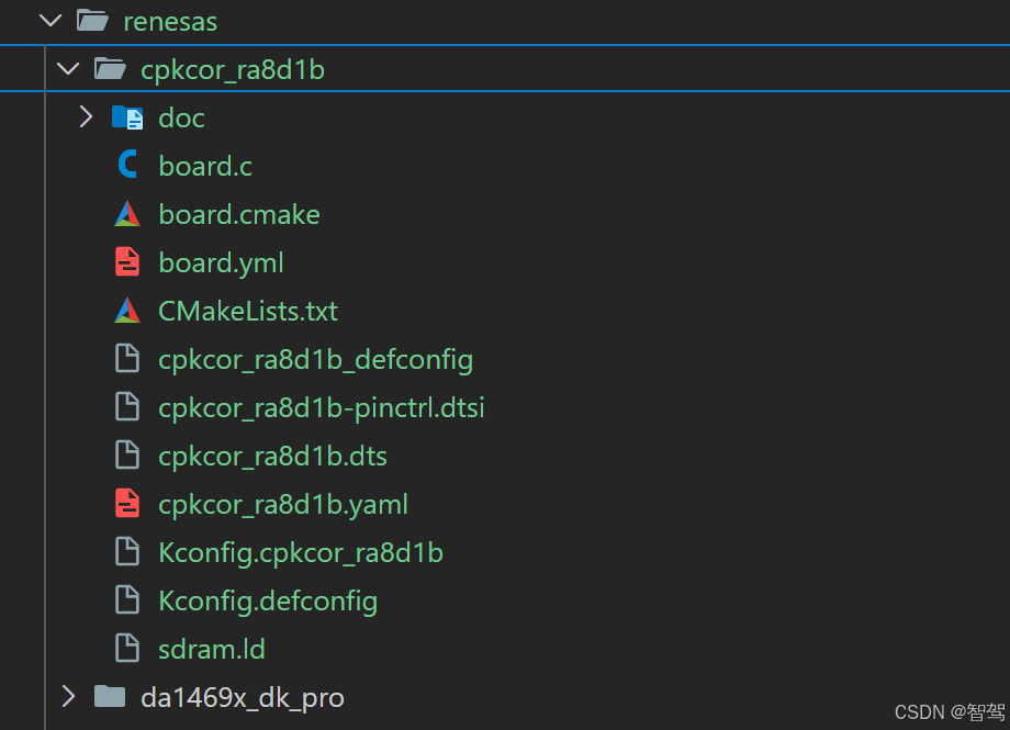
然后修改cpkcor_ra8d1b.dts文件,主要修改如下:
/*
* Copyright (c) 2024-2025 Renesas Electronics Corporation
* SPDX-License-Identifier: Apache-2.0
*/
/dts-v1/;
#include <renesas/ra/ra8/r7fa8d1bhecbd.dtsi>
#include <zephyr/dt-bindings/flash_controller/xspi.h>
#include <dt-bindings/gpio/gpio.h>
#include <dt-bindings/input/input-event-codes.h>
#include <zephyr/dt-bindings/memory-attr/memory-attr-arm.h>
#include <zephyr/dt-bindings/memory-controller/renesas,ra-sdram.h>
#include <zephyr/dt-bindings/adc/adc.h>
#include <zephyr/dt-bindings/gpio/dvp-20pin-connector.h>
#include <zephyr/dt-bindings/pwm/pwm.h>
#include "cpkcor_ra8d1b-pinctrl.dtsi"
/ {
model = "Renesas CPKCOR-RA8D1B";
compatible = "renesas,ra8d1b", "renesas,ra8";
chosen {
zephyr,sram = &sram0;
zephyr,flash = &flash0;
zephyr,console = &uart3;
zephyr,shell-uart = &uart3;
zephyr,entropy = &trng;
zephyr,flash-controller = &flash1;
zephyr,canbus = &canfd0;
zephyr,crc = &crc;
};
leds {
compatible = "gpio-leds";
led1: led1 {
gpios = <&ioporta 1 GPIO_ACTIVE_HIGH>;
label = "GREEN";
};
};
mikrobus_header: mikrobus-connector {
compatible = "mikro-bus";
#gpio-cells = <2>;
gpio-map-mask = <0xffffffff 0xffffffc0>;
gpio-map-pass-thru = <0 0x3f>;
gpio-map = <0 0 &ioport0 4 0>,/* AN */
<1 0 &ioport5 7 0>,/* RST */
<2 0 &ioport4 13 0>,/* CS */
<3 0 &ioport4 12 0>,/* SCK */
<4 0 &ioport4 10 0>,/* MISO */
<5 0 &ioport4 11 0>,/* MOSI */
/* +3.3V */
/* GND */
<6 0 &ioport9 7 0>,/* PWM */
<7 0 &ioport0 10 0>,/* INT */
<8 0 &ioport4 8 0>,/* RX */
<9 0 &ioport4 9 0>,/* TX */
<10 0 &ioport4 0 0>,/* SCL */
<11 0 &ioport4 1 0>;/* SDA */
/* +5V */
/* GND */
};
buttons {
compatible = "gpio-keys";
button0: s1 {
gpios = <&ioport0 8 (GPIO_PULL_UP | GPIO_ACTIVE_LOW)>;
label = "Push button switch 1";
zephyr,code = <INPUT_KEY_0>;
};
};
sdram1: sdram@68000000 {
compatible = "zephyr,memory-region", "mmio-sram";
device_type = "memory";
reg = <0x68000000 DT_SIZE_M(32)>;/* 256 Mbits */
zephyr,memory-region = "SDRAM";
status = "okay";
};
renesas_mipi_connector: mipi-connector {
compatible = "renesas,ra-gpio-mipi-header";
#gpio-cells = <2>;
gpio-map-mask = <0xffffffff 0xffffffc0>;
gpio-map-pass-thru = <0 0x3f>;
gpio-map = <14 0 &ioport5 11 0>,/* IIC_SDA */
<15 0 &ioport4 4 0>,/* DISP_BLEN */
<16 0 &ioport5 12 0>,/* IIC_SCL */
<17 0 &ioport5 10 0>,/* DISP_INT */
<18 0 &ioporta 1 0>;/* DISP_RST */
};
ek_ra8d1_parallel_graphics_expansion: parallel-graphics-expansion {
compatible = "renesas,ra-parallel-graphics-header";
#gpio-cells = <2>;
gpio-map-mask = <0xffffffff 0xffffffc0>;
gpio-map-pass-thru = <0 0x3f>;
gpio-map = <1 0 &ioport4 4 0>,/* DISP_BLEN */
<2 0 &ioport5 11 0>, /* IIC_SDA */
<3 0 &ioport5 10 0>, /* DISP_INT */
<4 0 &ioport5 12 0>, /* IIC_SCL */
<6 0 &ioporta 1 0>; /* DISP_RST */
};
dvp_20pin_connector: dvp-20pin-connector {
compatible = "arducam,dvp-20pin-connector";
#gpio-cells = <2>;
gpio-map-mask = <0xffffffff 0xffffffc0>;
gpio-map-pass-thru = <0x0 0x3f>;
gpio-map = <DVP_20PIN_PEN 0 &ioport7 4 0>,
<DVP_20PIN_PDN 0 &ioport7 5 0>;
};
aliases {
led0 = &led1;
sw0 = &button0;
mipi-dsi = &mipi_dsi;
watchdog0 = &wdt;
sram-ext = &sdram1;
};
zephyr,user {
i3c-pullup-gpios = <&ioportb 2 GPIO_ACTIVE_LOW>,
<&ioport7 11 GPIO_ACTIVE_LOW>;
};
};
&xtal {
clock-frequency = <DT_FREQ_M(24)>;
mosel = <0>;
#clock-cells = <0>;
status = "okay";
};
&subclk {
status = "okay";
};
&pll {
status = "okay";
/* PLL */
clocks = <&xtal>;
div = <4>;
mul = <160 0>;
pllp {
status = "okay";
};
pllq {
status = "okay";
};
pllr {
status = "okay";
};
};
&pll2 {
status = "okay";
clocks = <&xtal>;
div = <4>;
mul = <160 0>;
pll2p {
status = "okay";
freq = <DT_FREQ_M(480)>;
div = <2>;
};
};
&sciclk {
clocks = <&pllp>;
div = <4>;
status = "okay";
};
&canfdclk {
clocks = <&pllp>;
div = <6>;
status = "okay";
};
&lcdclk {
clocks = <&pll>;
div = <2>;
status = "okay";
};
&octaspiclk {
clocks = <&pll2p>;
div = <2>;
status = "okay";
};
&uclk {
clocks = <&pllq>;
div = <5>;
status = "okay";
};
&i3cclk {
clocks = <&pllp>;
div = <3>;
status = "okay";
};
&ioport0 {
status = "okay";
};
&ioport1 {
status = "okay";
};
&ioport4 {
status = "okay";
};
&ioport5 {
status = "okay";
};
&ioport6 {
status = "okay";
};
&ioport7 {
status = "okay";
};
&ioport9 {
status = "okay";
};
&ioporta {
status = "okay";
};
&ioportb {
status = "okay";
};
&sci9 {
pinctrl-0 = <&sci9_default>;
pinctrl-names = "default";
status = "okay";
uart9: uart {
current-speed = <115200>;
status = "okay";
};
};
&sci4 {
pinctrl-0 = <&sci4_default>;
pinctrl-names = "default";
i2c4: i2c {
sda-output-delay = <300>;
noise-filter-clock-select = <1>;
bit-rate-modulation;
};
};
&sci3 {
pinctrl-0 = <&sci3_default>;
pinctrl-names = "default";
status = "okay";
uart3: uart {
current-speed = <115200>;
status = "okay";
};
};
&trng {
status = "okay";
};
&spi1 {
pinctrl-0 = <&spi1_default>;
pinctrl-names = "default";
status = "okay";
};
&i3c0 {
i2c-scl-hz = <DT_FREQ_K(400)>;
i3c-scl-hz = <DT_FREQ_M(4)>;
pinctrl-0 = <&i3c0_default>;
pinctrl-names = "default";
interrupts = <60 1>, <61 1>, <62 1>, <63 1>, <64 1>, <65 1>;
interrupt-names = "resp", "rx", "tx", "rcv", "ibi", "eei";
status = "okay";
};
&flash1 {
partitions {
compatible = "fixed-partitions";
#address-cells = <1>;
#size-cells = <1>;
storage_partition: partition@0 {
label = "storage";
reg = <0X0 DT_SIZE_K(12)>;
};
};
};
&pwm3 {
pinctrl-0 = <&pwm3_default>;
pinctrl-names = "default";
interrupts = <51 12>, <52 12>;
interrupt-names = "gtioca", "overflow";
cam_clock: pwmclock {
compatible = "pwm-clock";
status = "disabled";
#clock-cells = <1>;
clock-frequency = <24000000>;
pwms = <&pwm3 0 PWM_KHZ(24000) PWM_POLARITY_NORMAL>;
};
};
&pwm7 {
pinctrl-0 = <&pwm7_default>;
interrupts = <40 1>, <41 1>;
interrupt-names = "gtioca", "overflow";
pinctrl-names = "default";
status = "okay";
};
&canfd_global {
status = "okay";
canfd0 {
pinctrl-0 = <&canfd0_default>;
pinctrl-names = "default";
rx-max-filters = <16>;
status = "okay";
};
};
&iic1 {
#address-cells = <1>;
#size-cells = <0>;
clock-frequency = <DT_FREQ_M(1)>;
pinctrl-0 = <&iic1_default>;
pinctrl-names = "default";
};
ð {
local-mac-address = [74 90 50 B0 5D E9];
status = "okay";
phy-handle = <&phy>;
};
&mdio {
pinctrl-0 = <ðer_default>;
pinctrl-names = "default";
status = "okay";
phy: ethernet-phy@5 {
compatible = "ethernet-phy";
reg = <5>;
status = "okay";
};
};
&usbhs {
pinctrl-0 = <&usbhs_default>;
pinctrl-names = "default";
maximum-speed = "high-speed";
status = "okay";
zephyr_udc0: udc {
status = "okay";
};
};
&usbhs_phy {
phys-clock-src = "xtal";
};
&adc0 {
status = "okay";
pinctrl-0 = <&adc0_default>;
pinctrl-names = "default";
};
&dac0 {
pinctrl-0 = <&dac0_default>;
pinctrl-names = "default";
status = "okay";
};
&port_irq12 {
interrupts = <88 12>;
status = "okay";
};
&port_irq13 {
interrupts = <89 12>;
status = "okay";
};
&sdram {
pinctrl-0 = <&sdram_default>;
pinctrl-names = "default";
status = "okay";
auto-refresh-interval = <SDRAM_AUTO_REFREDSH_INTERVEL_10CYCLES>;
auto-refresh-count = <SDRAM_AUTO_REFREDSH_COUNT_8TIMES>;
precharge-cycle-count = <SDRAM_AUTO_PRECHARGE_CYCLE_3CYCLES>;
multiplex-addr-shift = "10-bit";
edian-mode = "little-endian";
continuous-access;
bus-width = "16-bit";
bank@0 {
reg = <0>;
renesas,ra-sdram-timing = <SDRAM_TRAS_6CYCLES
SDRAM_TRCD_3CYCLES
SDRAM_TRP_3CYCLES
SDRAM_TWR_2CYCLES
SDRAM_TCL_3CYCLES
937
SDRAM_TREFW_8CYCLES>;
};
};
&ceu {
pinctrl-0 = <&ceu_default>;
pinctrl-names = "default";
interrupts = <53 12>;
interrupt-names = "ceui";
clocks = <&pclka MSTPC 16>, <&cam_clock 0>;
clock-names = "pclk", "cam-xclk";
burst-transfer = <256>;
};
zephyr_lcdif: &lcdif {};
zephyr_mipi_dsi: &mipi_dsi {};
renesas_mipi_i2c: &iic1 {};
pmod_sd_shield: &sdhc1 {};
dvp_20pin_i2c: &iic1 {};
dvp_20pin_interface: &ceu {};
&usbfs {
pinctrl-0 = <&usbfs_default>;
pinctrl-names = "default";
maximum-speed = "full-speed";
};
&wdt {
status = "okay";
};
&ulpt0 {
status = "okay";
timer {
status = "okay";
};
};
&ulpt1 {
status = "okay";
timer {
status = "okay";
};
};
&ospi0 {
pinctrl-0 = <&ospi0_default>;
pinctrl-names = "default";
status = "okay";
s28hl512t: ospi-nor-flash@90000000 {
compatible = "renesas,ra-ospi-b-nor";
protocol-mode = <XSPI_OCTO_MODE>;
data-rate = <XSPI_DTR_TRANSFER>;
ospi-max-frequency = <DT_FREQ_M(200)>;
reg = <0x90000000 DT_SIZE_M(64)>;
write-block-size = <1>;
status = "okay";
pages_layout: pages_layout {
pages_layout_4k: pages_layout_4k {
pages-count = <32>;
pages-size = <DT_SIZE_K(4)>;
};
pages_layout_128k: pages_layout_128k {
pages-count = <1>;
pages-size = <DT_SIZE_K(128)>;
};
pages_layout_256k: pages_layout_256k {
pages-count = <255>;
pages-size = <DT_SIZE_K(256)>;
};
};
partitions {
compatible = "fixed-partitions";
#address-cells = <1>;
#size-cells = <1>;
partition@0 {
label = "nor";
reg = <0x00000000 DT_SIZE_M(64)>;
};
};
};
};
&crc {
status = "okay";
};
mikrobus_serial: &uart3 {};
mikrobus_spi: &spi1 {};
修改完成后,我们可以简单测试下:
west build -p always -b cpkcor_ra8d1b .\\samples\\hello_world
west flash
连接串口,查看测试结果: 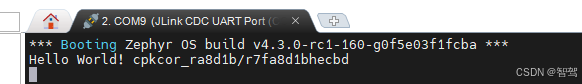


评论前必须登录!
注册